
Lift Axle Spec'ing 101Ordering Lift Axles with Confidence
Navigating the complexities of lift axles is crucial in today’s vocational trucking landscape, where maximizing payload not only enhances efficiency, but is also a critical factor driving profitability. When it comes to spec’ing a lift axle, there are many aspects truck body builders and fleet operators must consider. From state and federal weight regulations to terminologies needed to communicate effectively with suppliers and installation technicians, as well as the in-depth intricacies of selecting the right axle specifications, a multifaceted perspective is necessary to find the lift axle that will work best for your application. Let’s dive into everything you’ll need to know to spec your next lift axle.
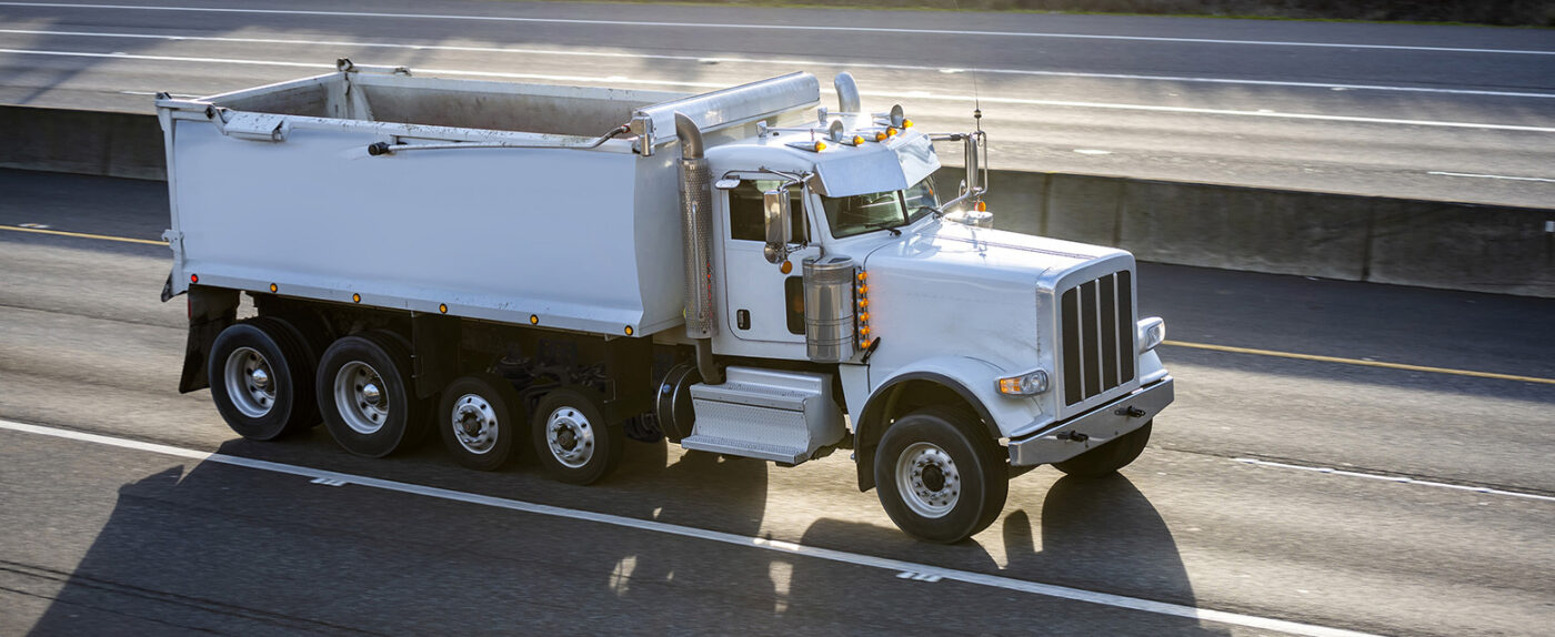
Federal vs. State Weight Limits & Regulations
The first key to finding the perfect lift axle for your operation is understanding the interplay between federal and state regulations and the complexities of weight limits on interstate highways. The Surface Transportation Assistance Act of 1982 established a uniform maximum weight limit of 80,000 pounds gross, 20,000 pounds for single axles, and 34,000 pounds for tandem axles. This legislation aimed to streamline weight regulations across state lines, simplifying compliance for long-haul trucking operations. The Federal-Aid Highway Act of 1956 and the subsequent Federal-Aid Highway Amendments of 1974 allow states to set a weight limit above the federal standards, whereas prior to the 1982 act, states could set lower limits. These regulatory foundations not only unified weight limits but also highlighted the importance of understanding how state regulations can differ from federal standards, particularly for vehicles that traverse multiple jurisdictions.
Fleet managers planning to equip their vehicles for nationwide operation must consider the variances truckers and fleet operators will encounter when crossing state boarders. To ensure legal compliance, managers must equip their vehicles appropriately according to the state-specific legal weights set by transportation laws.

Additional Restrictions on Lift Axles by State
On top of federal and state weight regulations, fleet managers must also be aware of varying restrictions on lift axles imposed by several states across the U.S.. Some states either impose additional constraints on the use of lift axles, the placement of their air controls, or ban their use on state roads all together. As of the writing of this blog, the restrictions are as follows:
- Alaska: Lift axles within the power unit’s drive group aren’t considered when calculating the legally permissible weight.
- California: Regulations effectively restrict vehicles to a single lift axle, which must distribute weight within a ±10% range of the average axle load in its group.
- Georgia: The presence of a lift axle is not factored into the authorized gross weight calculation for any vehicle.
- Illinois: A limit is set for straight trucks, restricting them to a maximum of four axles.
- New York: Lift axles must be 20k Self Steer and bear a minimum of 80% of the load of any other axle in the group, as per DLN#14-01.
- Minnesota: Vehicles, either standalone or as part of a vehicle combination, are capped at four axles unless the additional axles are designed for steering or castering purposes.
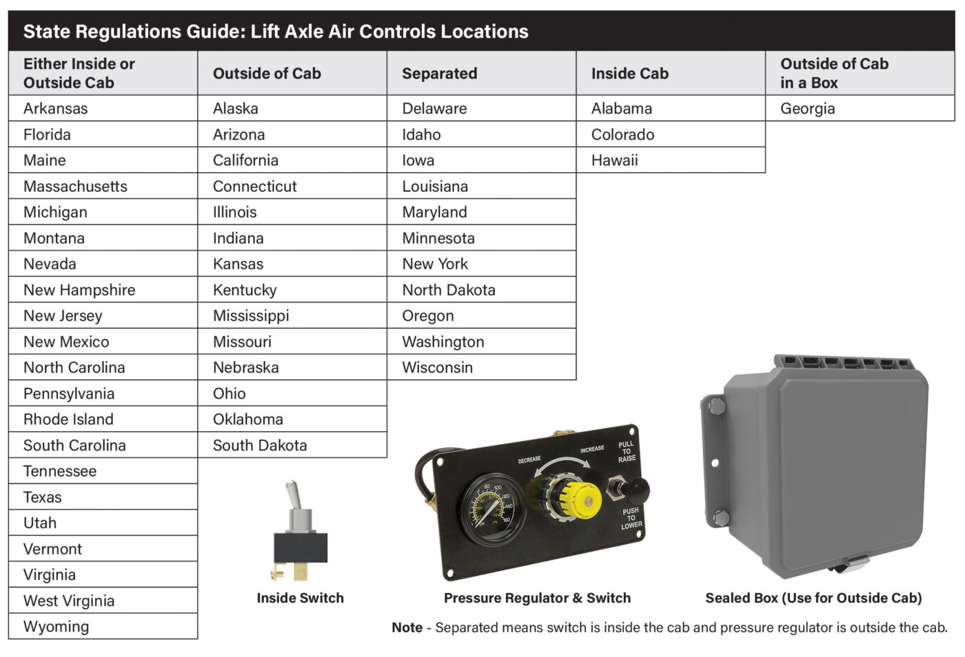
It’s important to note that these summaries are based on current Department of Transportation (DOT) data and are subject to change. Before you spec your lift axle, please consult directly with the relevant DOT websites for the most up-to-date and precise regulations.
Lift Axle Terminology
Before we get into the specifics of ordering a lift axle, it’s important to note crucial terms when it comes to understanding the operation and variations of available units.
- Center of Gravity (CG): This pivotal point represents where the cumulative mass of a vehicle effectively concentrates. Original Equipment Manufacturers (OEMs) provide maximum CG and GVW guidelines to body builders, aligning with braking system validations to meet FMVSS-121 standards. Exceeding these parameters requires additional brake system certification.
- Site or Creep Travel Rating: Vocational Axle and Suspension manufactures will usually provide a rating beyond the suspensions listed capacity for when the auxiliary axles are lifted in a construction site for maneuverability and traction. Ratings are typically limited to < 5mph and may also be limited to a percent of operation time.
- Travel: This measures the total vertical movement range of the lift axle, taken at the axle’s spindle centerline. It is an essential metric for ensuring proper clearance and functionality.
- Lift: This is the specific height that the lift axle can be raised off the ground. It’s a critical parameter for maintaining axle health and compliance with regulations.
- Caster Angle: This refers to the angle between the steering axis and the vertical axis of a wheel. Proper caster angle ensures that the wheel tracks straight and aligns with the motion of the vehicle.
- Pusher Axle: This term is applied to an auxiliary lift axle situated ahead of the drive suspension. A helpful mnemonic is to think of it as being ‘pushed’ by the main drive components.
- Tag Axle: In contrast, when the auxiliary lift axle trails behind the drive suspension, it earns the name ‘Tag’ Axle, as it ‘tags along’ after the main force.
- Self-Steer: These axles are designed with an inbuilt caster angle that allows them to align passively with the truck’s direction, eliminating the need to lift them on tight turns. However, this feature can cause complications when reversing, as the axle tends to swing out, requiring either an automatic lift mechanism triggered by the brake lights or a steer-lock feature to maintain control
- Non-Steer: Non-Steer axles remain in-line with the truck’s body. They are typically seen as less favorable due to the need to lift them during sharp maneuvers to avoid tire and pavement wear, which also leads to increased stress on the vehicle’s suspension system. However, non-steer axles contribute to the vehicle’s roll stability.
Spec’ing a Lift Axle
Now that we’ve covered the legalities and terms associated with lift axles, we can move onto the important part: Spec’ing a lift axle. When spec’ing an Auxiliary Lift Axle, having the right information at your fingertips is critical. If you’re leaning towards Link for your lift axle solutions, we simplify the process significantly. Our approach is direct and customer-oriented, allowing you to talk to one of our sales experts who can guide you through the decision-making process. To ensure the conversation is as fruitful as possible, Link suggests gathering 12 key pieces of information before the ordering, all of which are detailed in our comprehensive Order Guide.
Step 1
The first step in the guide is straightforward and asks you to make initial decisions such as the type of lift axle you require—pusher or tag, Non-Steer or Self-Steer— and the capacity needed. This step also considers the type of drive axle(s) suspension you are using. If you’re opting for a Non-Steer, determining the wheel configuration to ensure correct stud length is crucial.
Step 2
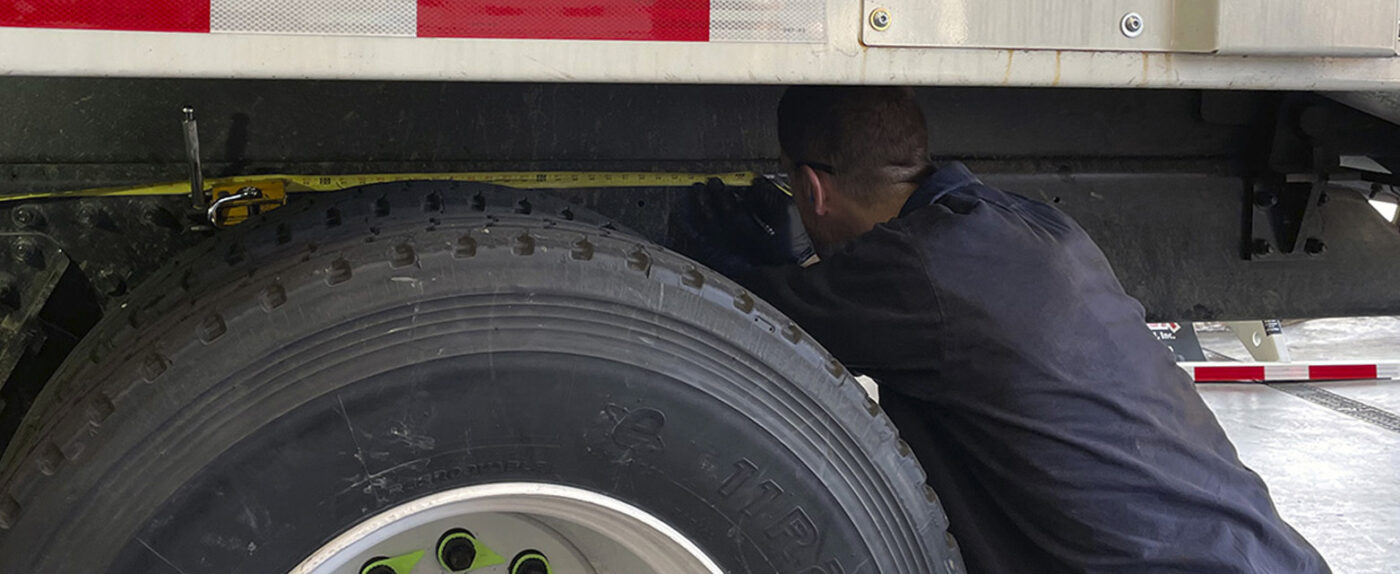
The second step requires more detailed information and involves taking precise measurements from the truck intended for the Auxiliary Lift Axle installation. An essential aspect here is obtaining an accurate frame height at the centerline of the future lift axle installation point. This measurement is essential in ensuring that the chosen lift axle will fit and perform as intended.
Ensuring accurate ride height:
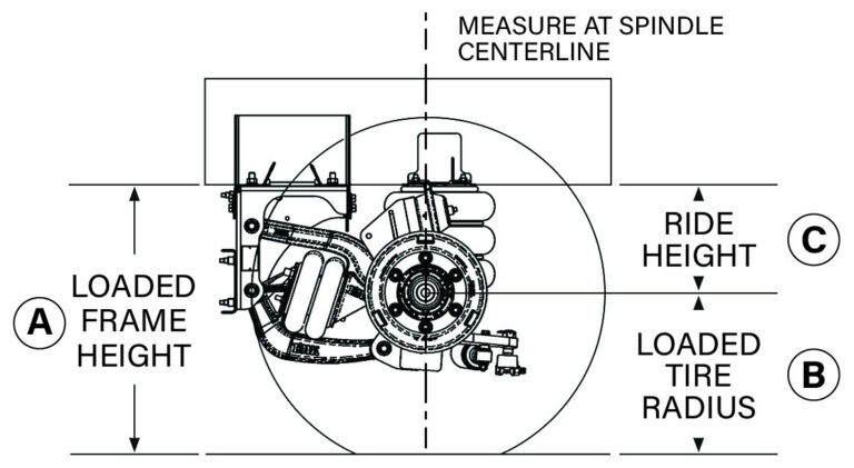
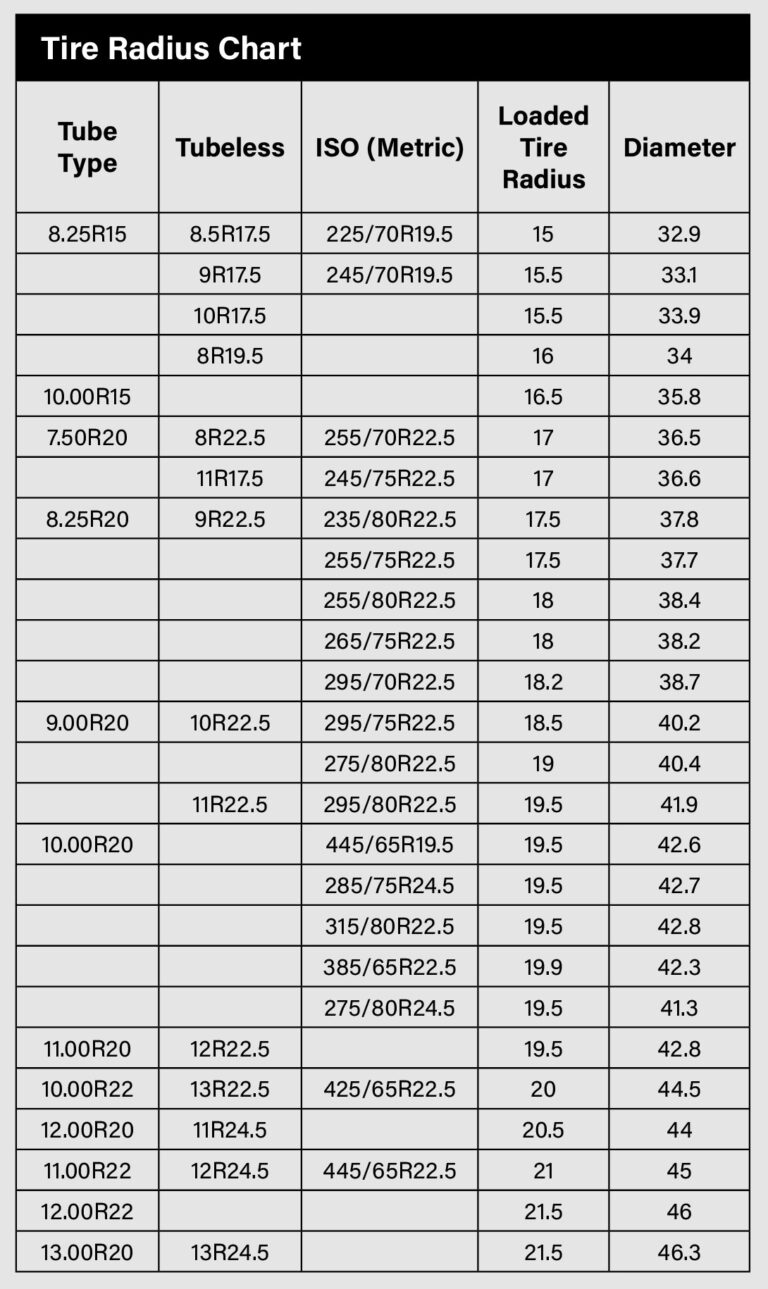
Ride Height with Loaded Truck:
A - B = C (Loaded Frame Height - Loaded Tire Radius = Ride Height)
1. For trucks that are fully loaded, you must record the ride height “A” while the vehicle is on level ground. If measuring with an unloaded truck is impossible, you may bypass the following steps.
2. Next, you will need to determine the loaded tire radius “B,” either by measuring it directly or by consulting the provided tire charts in Link’s Ordering Guide—precision here is vital, as rolling radius can differ substantially among tire models.
Ride Height Measurement for Unloaded Trucks:
A - B - D = C (Loaded Frame Height - Loaded Tire Radius - Additional Deflection = Ride Height)
1. Ensure the truck is positioned on level ground.
2. Record the frame height at the axle centerline, denoted as “A”.
3. Refer to the Link Ordering Guide to determine the loaded tire radius “B” for the specific tire model installed. Variations in rolling radius can affect measurements.
4. Consider additional deflection due to the suspension system and tire compression when the truck is not carrying a load, which is indicated as “D”.
Factoring in Suspension and Tire Deflection:
- Mechanical Drive Suspension: Allow an additional deflection (“D”) of 1.5 inches to account for both the suspension drop and drive axle tire deflection.
- Air Ride Drive Suspension: A deflection (“D”) of 1.0 inch is appropriate, as there is typically no suspension drop.
5. The unloaded ride height “C” is the resulting measurement after accounting for the tire radius and deflection: C=A-B-D.
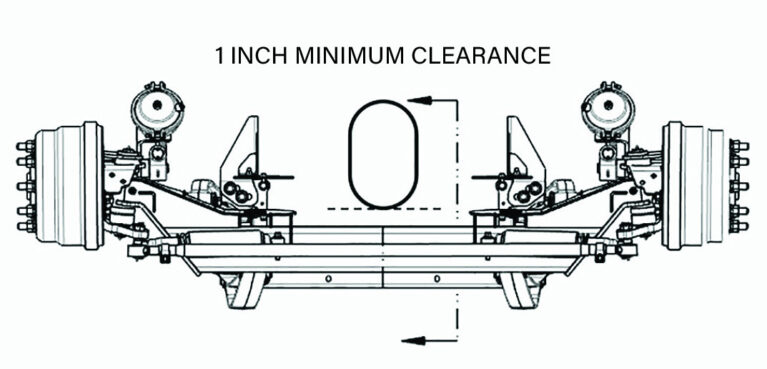
Driveshaft Location (Pusher Axle Position(s) Only)
When preparing to install a pusher axle, it’s crucial to determine the available space around the driveshaft to avoid any interference. This involves a precise measurement from the lowest part of the truck’s frame to the bottommost point of the driveshaft at the specific location where the centerline of the pusher axle’s suspension will intersect with the driveline. Recording this distance ensures that the pusher axle can be fitted without impeding the driveshaft’s operation, allowing for optimal performance and safety.
Step 3:
The final step in spec’ing your lift axle is deciding on which type of air control system will work best with your application. Most buyers opt to purchase air controls along with their lift axle, favoring the integrated approach. Choosing an integrated air control system provides several benefits, thanks to the expertise and attention to detail from our skilled team.
The Integrated Solution provides several advantages:
- Precision Assembly: Our team members are seasoned in fitting and plumbing, handling numerous units daily. This experience allows for a streamlined process that includes rigorous quality checks, minimizing the likelihood of installation errors.
- Installation Efficiency: The integrated system significantly cuts down on installation time. By consolidating various outlets into a single hub, the process becomes far less complex.
- Simplified Connection: Once the lift axle unit is in place, connecting it to your vehicle is as easy as attaching air lines to our clearly marked, color-coded ports.
- Ensures sufficient air volume: The integrated air controls add value with additional air capacity for faster maneuverability and safety air supply.
Consider Additional Options
When completing your lift axle purchase, it’s essential not to overlook the variety of optional equipment available. These additions can significantly enhance the performance, functionality, and safety of your lift axle, whether it’s self-steer or non-steer.
Moving Forward with Lift Axles
In the complex and regulation-driven world of trucking, lift axles emerge as a pivotal solution, balancing compliance with state and federal laws and the ever-important need for increased productivity and profitability. While the journey from configuring a truck to ordering and installing the right lift axles might appear daunting, it’s a process made significantly smoother and more manageable thanks to the dedicated professionals at Link.
At Link, we don’t just supply lift axles; we offer a partnership. Our team is prepared to offer guidance on every step, ensuring that your choices are not only compliant, but are also optimal for your specific needs. Whether it’s helping you navigate through our detailed order guide, or advising on the best auxiliary lift axle specifications, our experts are a call away. Our team offers personalized assistance and answers to any questions you might have throughout the process, so we can help you spec the lift axle that will optimize safety, productivity and profitability for your application.
Blog Author
Kirt Weaver
North American Sales Manager – Fleets


